


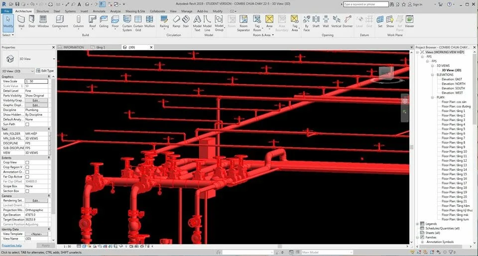
Schematic Diagram of the Automatic Fire Fighting System and Installation Method
Sprinkler Fire Extinguishing System:
It is a set of specialized devices used to extinguish fires automatically, without human intervention. The Sprinkler fire extinguishing system uses water or foam to put out fires, so these systems are typically installed at the overhead areas of the space being protected.
Arrangement of Sprinkler Heads and Technical Specifications:
-
Sprinkler heads oriented upward are installed on the 1st floor, and those oriented downward are used for floors 2 through 13. The spacing between sprinkler heads is 3–4 meters.
-
The determination of calculation parameters — such as water discharge intensity, spray density, area for flow calculation, coverage area per sprinkler, distance between heads, and system operation time for water-based fire extinguishing — must follow Table 2 of TCVN 7336‑2003
Piping Network:
-
Pipes supplying the Sprinkler heads are sized D25 – D80. The main water supply uses black steel pipes of sizes D125, D100. The fire water supply pipe (D100) runs from the pump room to the 1st floor. Here, the D100 fire water supply line is connected in a ring (loop) to ensure sufficient fire water pressure for both the automatic Sprinkler system and wall-mounted fire hose systems.
-
We design two vertical piping risers (D100), connected as a ring loop supplying the Sprinkler network from the 1st floor up to the 13th floor. From this D100 loop, reducers are used to branch off to pipes of D80, D65, which then supply the Sprinkler heads via branch pipes of D50, D32, and D25.
-
In addition to the vertical looped piping network (D100, D80), the system is connected to a fire department inlet (hydrant) sized D100 with two outlets of D65 for fire trucks. This hydrant connection (fire brigade inlet) conforms to current fire truck requirements with D100 pipe.
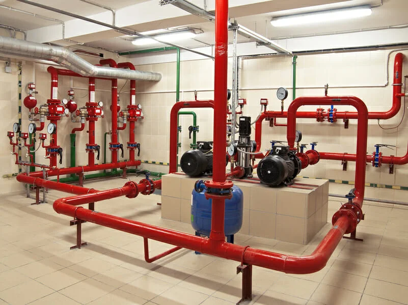
Pump System and Operation Principle:
-
To supply water and maintain pressure in the entire Sprinkler piping network, we use a pump assembly including:
-
One electric motor-driven main fire pump
-
One electric motor-driven standby fire pump
-
One pressure‑compensating pump (also known as jockey pump) to maintain stable pressure in the piping network
(Details are shown on the design drawings.)
-
-
Pump activation and shutdown can be done automatically or manually. In automatic mode, activation is done via pressure switches or triggered by the fire alarm system.
-
When system pressure drops to 90% of the setpoint, the pressure switch starts the jockey pump. A relay controlling a minimum runtime is included in the pump control system to prevent the jockey pump from cycling on/off too frequently.
-
If pressure falls to 80% of setpoint, the jockey pump stops and the main fire pump is started (the pre‑selected duty pump). If the main pump fails or does not operate, and pressure continues to fall to 70%, the standby fire pump will start.
-
In manual mode, pumps can be started via the pump control panel.
-
All pumps are located in a common pump room of the building. The pump room is situated on the 1st floor.
-
Power supply for the pumps is taken from a priority power source (connected ahead of the main switch), and also backed up by the building’s generator.
Other Components:
a. Dedicated control valve assembly for the Sprinkler system:
-
Main shut‑off valve and auxiliary shut‑off valve with open/closed status indicators.
-
Pressure gauges displaying system pressure before and after the valve assembly.
-
Test drain valve.
-
Pressure switch.
b. Flow Switch:
-
Flow switches are installed on floors as shown in design drawings. The switch body and base are made of die‑cast aluminum. A rubber gasket is placed between the base and cover. The contact leaf can be adjusted to suit on‑site dimensions. A time delay device adjustable from 0‑60 seconds is included to prevent false alarms caused by sudden pressure surges. The flow switch signal is sent to the central control room to indicate whether there is water flow through the fire pumps, and the state of the Sprinkler system it manages.
c. Pressure Gauges:
-
Installed at the pump room and on the Sprinkler test riser to report pressure at each point, especially at the highest and farthest points.
d. Pressure Vessel:
-
The pressure vessel ensures stable pressure for the pressure switch. It is located in the pump room and connected to the piping network. The pressure switch mounted on the vessel controls the operation of the jockey pump. The pressure vessel is chosen to be 200 liters, manufactured by G7 countries.
f. Shut‑off Valves:
-
Shut‑off valves are installed in the fire water piping network with diameters D125, D100, D80, D65, D50, D32, D25, D15. All major equipment in the system is selected to meet the Vietnamese fire safety standards.